When I am about to spend a lot of time repairing or modifying an amplifier, the first thing I do is redraw the schematic. Usually, this is a very quick sketch on a piece of scrap paper. Sometimes I draw the whole circuit, but more often I just focus on the portion I’m most concerned with.
I do this because schematic drawings are subjective. They emphasize what its designer thought was important, usually to the detriment of things considered less important. Forty or fifty or seventy years later, I have different priorities than the techs and engineers who originally built and maintained the amplifier. The original schematics are perfectly fine for taking a quick glance at the circuit, but, under any other circumstances, I think it’s more efficient to use a cleaner drawing.
I recently started to digitize my schematic re-drawings, and I’ll be sharing them here. The first one is the Wurlitzer 112.
In redoing the 112 drawing, there was just one bit of ambiguity that I wanted to eliminate: Socket A. Although just two pins of Socket A are involved in 112’s circuit, the entire thing is depicted in loving detail. There are arrows pointing vaguely into space. There are even thicker arrows pointing from the “Socket A” labels to the socket itself, as if you might get it confused with a different socket.
All this suggests that Socket A has some importance to the circuit. It doesn’t. Socket A is the vestige of an exciting, revolutionary amp design that Wurlitzer ended up abandoning. But more on that in a minute. First: the schematic drawings.
To avoid slowing down your inbox, I made the following images very low-res. Printable high-res versions can be downloaded here.
THE ORIGINAL SCHEMATIC
This schematic definitely isn’t bad at all: it’s detailed, readable, and it has voltage info that a lot of schematics leave out. Unlike later Wurlitzer models, the 112 doesn’t have a wiring harness, which definitely cuts down on the visual clutter. However, I feel that there are two things that slow your eyes down when looking at the drawing:
The dashed lines connecting the two halves of each preamp tube. There were more tube types available in the 1950s than there are today, many of which were composed of one triode in a single glass envelope. In that respect, it may have been helpful to indicate that the two preamp tubes are, in fact, dual-triode types. Today, though, most preamp tubes are in the 12A[*]7 family, and it is typical to wire successive gain stages in adjacent triodes. So, in the 112 amp, the relationship between the triodes is understood, and does not have to be depicted with dashed lines. I omitted them in my version of the schematic.
The depiction of Socket A and Plug A between the first and second gain stages. I feel that this adds excessive complexity to an extremely simple part of the circuit. As I’ll explain below, Socket A is a design hiccup. Although its detailed schematic drawing makes it seem really important to the circuit, it’s not. Perhaps it was drawn like that to conceal the fact that Socket A simply represents a false step, a path that was explored but ultimately rejected.
THE NEW SCHEMATIC
Because this is just a straightforward reproduction of the original schematic, I didn’t modify the circuit at all in my drawing. But, when restoring the amp itself, there are changes that I recommend making. Most importantly, I would update the two-prong power receptacle to three-prong, and make sure both the switch and the fuse are mounted on line, not neutral. I also make a few other changes, which reduce noise and increase gain. I’ll talk more about that later this week.
Since only two pins of the socket are used in the circuit, I wrote those pin numbers into the drawing. (Some components use pin 1 as a ground, but this is just for convenience. The grounds in this amp are largely arbitrary.) However, I did not depict the socket itself.
WHY IS THE OCTAL SOCKET THERE AT ALL?
The 112’s octal socket is pretty mysterious. On the schematic, it’s labeled “Socket A,” although there are no other sockets on the amp that it might be confused with. Although all pins are depicted, only three are in use, and one of them is simply grounded to the chassis on the socket’s own mounting ring. The other two pins lead into the socket and right back out, via a capacitor and a resistor, like an ornamental detour on a walking trail. These components don’t need shielding, or anything like that. They could easily exist inside the chassis with the other components.
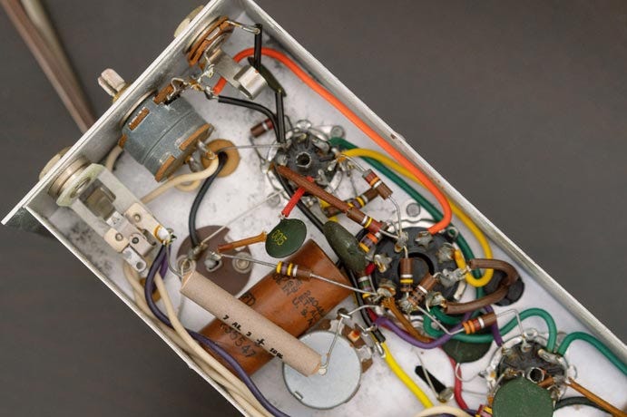
In this era, octal sockets are used as wiring harnesses, but Socket A does not lead to a harness. It terminates right on the chassis, its plug end enclosed by a smooth black dome. If you pry the dome off with a screwdriver, you will find a small ceramic capacitor and a carbon resistor. As we can see from the schematic, these components are in the signal path. For that reason, pull the plug from the socket will cut signal.
Socket A has no practical use for the circuit or the piano as a whole. Its capacitor, C4, is a coupling capacitor, which allows signal to pass to the next stage while blocking DC plate voltage. The circuit requires this capacitor, and it is found in every tube amplifier. The 470k resistor, R20, is more unusual. It appears in series with the 500k volume pot. This increases signal attenuation at every position of the pot, even when it is turned to full volume. A 500k pot is not half as loud as a 1M pot—the differences between them are more tonal than anything else. But, in this case, the resistor basically makes the 500k pot into a 1M pot that can’t be turned up past 5.
Aside from attenuation, R20 has tonal consequences as well. At low or medium volumes, a potentiometer’s large series resistance tends to roll off highs. This is why 1M pots often have bright caps on them. The bright cap allows high frequencies to bypass the pot’s series resistance when the pot is turned to low volumes. At high volumes, the bright cap is less important, because there is less series resistance. (Remember that a 1M pot turned to 2 is like an 800k resistor in series with the signal, and a 200k resistance to ground. If turned to 8, the resistances are flipped: 200k in series, and 800k to ground. More on how pots work here.)
R20 ensures that the 112’s volume pot always has a large series resistance, even when turned to full volume. This is unusual, and it means that the amp’s tone will be comparatively dark at all positions of the volume knob. Wurlitzers tend to have a lot of natural low end, and engineering decisions like R20 tend to emphasize that. (There are ways to make the circuit brighter, which I’ll explain in a later newsletter.)
So, the 112 has a mysterious octal plug containing a very mundane capacitor and a tone resistor that nobody would ever need or ask for. Neither component needs to be protected or separated from the rest of the circuit for any reason. There is room inside of the chassis to mount both. So, why does the plug exist, and why did Wurlitzer put these two components inside of it?

The answer is in the 112’s patent drawings. It turns out that the electronic piano was originally intended to be a much more ambitious instrument: more like an organ or a synthesizer, with modular amplifier effects that would be sold separately, for users to buy according to their taste and budget. The effects units would mount next to the main amp, and connect through an octal plug. The effects would be controlled by up to six extra knobs, mounted on the keyboard’s front panel. (I have written about the patent here, and on Wurlitzer patents in general here.)
This likely explains why the 112 amplifier is built more powerfully than later amplifiers, with two preamp tubes’ worth of gain stages. Whenever signal is routed out of an amplifier and passed through effects, it needs to be amplified again before it reaches the power amp. The 112 has plenty of gain stages following Socket A that are capable of bringing an effected signal back up to full power.

Wurlitzer clearly abandoned the modular plan somewhere between the patent drawing and the production of the 112. Of course, just because something is patented doesn’t mean that the holder has any plan to produce it. Companies will occasionally patent products just to block competitors from manufacturing anything similar. This is possible because the patent gives its holder an exclusive right to use or license the technology.
However, here, the Wurlitzer’s modular design clearly made it further than the concept stage. Every 112 chassis has a socket. It just doesn’t have anything to plug into it.

Was Wurlitzer still leaving open the possibility of manufacturing add-ons to the 112 amp? Maybe. As you can see in the photo above, the 6.3 V heater winding and the power supply—at the juncture of R15, R5, and R22—both mount on the socket, using pins 8 and 4, respectively. As stated above, pin 6 is essentially an output—it provides a path out of the chassis. In the 112 circuit, it just goes out into the dome and comes straight back into the chassis, through pin 5, which connects to the volume pot.
The 112, as built, doesn’t put any of this to use—outside of using the dome as the world’s most boring tone loop. However, the arrangement inside the chassis gives you everything you need to send the amp’s power and signal into an auxiliary amp. The auxiliary amp could draw heater current by tapping pin 8, and power supply voltage by tapping pin 4. Pin 6 is an output—a “send,” to use the language of an effects loop—and pin 5 is an input—a “return.”
So, although the schematic doesn’t fully show it, the point-to-point layout of the 112 does allow for an auxiliary amp to connect at Socket A. This is, essentially, an effects loop—which is really impressive, since effects pedals were, arguably, yet to be invented. (The DeArmond Tremolo Control was an early innovation, released in the late 1940s, but it occupied a lonely place in the market for the next couple of decades.)
Today, effects loops just send the signal in and out of the amplifier. The pedal itself is responsible for providing any supply voltage that its circuit requires. But, without readily-available small-signal transistors—an invention of the 1960s—effects pedals would need to be tube-powered. This would make them just as hot, expensive, and heavy as the amplifier itself. The 112 solved this problem by sending out not just signal, but supply voltage too. Supply voltage can’t be done with 1/4” jacks, which weren’t even standardized at this point anyway. (Case in point: the 112’s aux output jack is 0.210”.) This needed a wiring harness. Hence, Socket A.
Because today’s effects pedals use 1/4” jacks, they can be daisy-chained with any other pedal and connected to any amplifier. The fact that there is nothing proprietary about pedal connections helps keep the pressure off individual manufacturers. Big manufacturers maintain a full line of pedals; small manufacturers might release just one or two, and cater to a niche. Customers can mix and match and buy from everyone. This ecosystem is healthy, and manufacturers enjoy a relatively low barrier to entry.
Now imagine the Wurlitzer company’s position in 1955. They have invented an effects loop before the existence of effects pedals. The pedals must take their supply voltage from the 112’s amplifier, through an octal plug whose wiring must match the socket on the amp. The amplifier is not a guitar amplifier, but instead is part of an electronic piano that has never been tested in the market before.
None of these pedals have been invented yet. The Wurlitzer Co. will have to invent them all. No other company is going to help them out—the pedal ecosystem doesn’t exist yet. What kind of effects should Wurlitzer develop first? The patent mentions a few ideas: “novel plug-in circuits” for “varying the response characteristics of the amplifier", a tremolo unit, “musical effects” like “simulated” bass viola and celeste, and “many novel musical effects.” (In a patent application, you want to include all the ideas you have, even if they’re a little redundant.) How many customers, after dropping $300 ($3300 today) on an electronic piano, really want to pay extra to make it sound like a bass viola? Are these add-on units worth the cost of designing and prototyping?
So, it’s probably not surprising that the modular concept was abandoned. And, since it was, I left the socket out of the schematic drawing.
PROTECTING THE REED BAR VOLTAGE FROM CURRENT-HUNGRY AUXILIARY AMP TUBES
The 112 amp has another unusual feature that might also be related to Socket A. In later Wurlitzer amplifiers, each power supply filter node is in series with the next one. The reed bar voltage is at the very end, giving it the benefit of every filter capacitor that comes before. However, in the 112, the power supply splits into two parallel paths after R16. In one path, the supply voltage goes through R15, and leads to V1, the input 12AU7. In the second path, the supply voltage goes through R29, supplying 140 V to the piano input.
Compared to a 12AX7, 12AU7s draw a lot of plate current. Generally, the more current the tube draws, the less voltage is available for the next stage. Because the 112 uses 12AU7 preamp tubes, putting the reed bar voltage on a parallel node helps keep the reed bar voltage high. Higher reed bar voltage is desirable because it gives the signal a little more headroom.
As you can see from the schematic, the voltage for V1 drops from 205 V to 105 V after R15. This is low, but usable (some models of Wurlitzer send as low as 80 V to the reed bar). However, if tubes from an auxiliary amp also tap into the reed bar voltage at the R15/C9 node, that would bring the supply voltage down even further—depending on tube type, possibly too low to power the reed bar at all. Supplying the reed bar from that parallel node helps ensure that it receives a consistent voltage, regardless of what might be connected to Socket A.


